Golden Hammer
- the company history
Recently Added
or Updated...
Christchurch Chapel, Bridgwater
Recollections, Info,
Memories, Explanations
---------------------
Queen Elizabeth II acceded to the throne on the death of her father, George VI on the 8th February 1952. On 2nd July 1952 she visited the Royal Show at Stover Park, Newton Abbot.
The 1952 Royal Agricultural Show of England, the Royal Show was held, for the first time ever, near Newton Abbot, at Stover Park. Her Majesty was the first monarch to visit the town since 1625 and with her attendance and the excellent weather the crowds turned out in great numbers. The show extended over 4 days, 1st - 4th July.

The only blight on the proceedings was the cancellation of entries of cattle, sheep and pigs because of the Foot and Mouth Disease. By August of 1952 over 1,900 outbreaks had been recorded and in total a loss of 128,000 animals (cattle + sheep + pigs).
To compensate for the empty pens the organisers, with about 14 days notice, persuaded over fifty manufacturers and engineering firms whose products were produced within Devon and within easy reach of the showground, to create an Exhibition ‘Devon Reports Progress’ – the purpose was to show some of the varied activities of Devon Engineering firms with the emphasis on post war developments and the contribution to the Export Drive.

The Exhibition had the following sections.-
Agricultural & General Engineering
Implement Parades
Woodworking Machinery
Ditching & Thatching
North Devon Water Board
Large Exhibits.
Garton & King’s huge 9 foot diameter 3 ton gear was definitely a contender for the last category! This was part of an order from the British owned Bamberton Cement Plant in British Columbia, Canada (see below). This large gear ring was moulded by Dick Lomas and was machined by Harold Williams (see below).
Garton & King’s stand had a display of some of the other gears and wheels that they manufactured at that time, and the first image below shows a variety of gears under the stand canopy – unfortunately the notices attached are illegible. The images (if you look carefully) also show that the display included a couple of Manhole Covers and a large valve used in the Paper Making Industry (Hele, Silverton & Ivybridge Mills come to mind). The Golden Hammer was also having a Day at the Show and can be seen on display in the centre image.
 - click to enlarge")
 - click to enlarge")

Three views of the G & K stand

Other firms with engineering exhibits included Glanville & Sons of Bovey Tracey, agricultural engineers, G.M. Engineering of Otter Mill, Ottery St Mary, electrical control equipment, Hobart Manufacturing Co. Ltd (Frandor Engineering) of Barnstaple, food mixing machines and food preparing machinery; and the Harper Aircraft Company of Exeter Airport who exhibited their Type CH3, Series 4 ‘Skyjeep’ single engine high winged Monoplane.
The original Plan of the Showground was printed in the belief that cattle, pigs and sheep would be exhibited; this did not prove to be the case but the map was not reprinted. Working on the basis of the images I have acquired, the location of the G & K stand is near to where the Heavy Horses are indicated. Part of the Plan (right) indicates where this was, in the area east of the A282 within the grounds of Stover House (then and still now a School). Actually there were four stands, numbered 83, 84, 85 & 86, and I personally have had access to the area (currently still pasture) in which I am almost certain that the company had their Stand.
The following four images are out of copyright and show the Queen approaching the area where the Heavy Horses were on show. On the extract from the Show Plan is marked a Café – the concession for catering was won by H & C Simonds of Reading and the last letters of their name can be seen in the first image of the Queen to the left. It has been confirmed by Raymond Simonds that the company did indeed have their name emblazoned on their Marquees.
 Queen Elizabeth II at the Royal Show |
 The sign at top right would have read ‘Devon Reports Progress’ and beneath that text ‘Engineering Exhibition.’ A glimpse of G & K’s Gear can be seen halfway up the right hand edge of the image. |
|
  In these two images, taken seconds apart, we show the Queen inspecting the Heavy Horses. Garton & King's Gear is at head height in both images |
||
Although called to serve in H.M. Forces in 1945, Harold Williams joined Messrs Taylor & Bodley as an apprentice at the age of 14. After the War Taylor & Bodley moved to Tan Lane and on being demobbed he joined Garton & King as a Fitter and Turner.

Harold Williams (who machined the large Gear) at a lathe in the Machine Shop.
He describes the works as consisting of the following: the Main Foundry Area where Iron, Aluminium, Brass & Phosphor Bronze were cast, the Pattern Shop (carpentry), a Core Shop (used in castings) and a Fettling Shop where, amongst other things, castings were cleaned, a Blacksmith’s Shop for forgeing and welding and a Pipe Fitting and Plumbing Shop. There were also the Offices (upstairs) and the Stores.

A view of the Machine Shop at the Tan Lane Foundry.
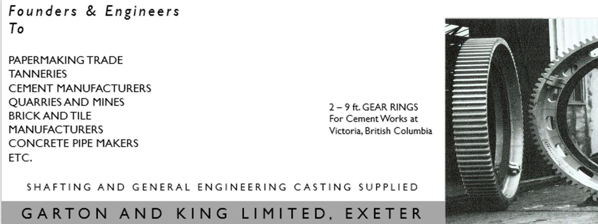
The Company’s expertise in producing Gears of all kinds has often been overlooked by the general public throughout most of the 20th century. Joe Public’s general knowledge of the Company’s products centred around the products beneath their feet, the ubiquitous Manhole Covers that flaunted the name or, on the Domestic Front, the celebrated AGA Cooker or Bendix Washing Machine. If you were a Builder or Surveyor you’d probably be aware of the Heating and even the electrical and plumbing side of the business. If, however, your business centred around the Papermaking, Tannery, Brickmaking, Cement or Quarrying Trades and Industries then you would in all probability associate the company with Gears of all types, kinds and sizes.
Here are the ‘innards’ of a leaflet published by the Company sometime prior to 1957, judging by the telephone number stated on the outside of the leaflet as Exeter 3904 - around about 1957 it changed to 54945 and survives to this day (with an added 2) as the number for 19 North Street Showroom of Garton King Appliances. As can be seen in the top left image on the leaflet the gears manufactured came in all sizes. The largest gears were for the Cement Industry, one customer being Bamberton Cement in British Columbia. These are doubtless the ones that attracted the most attention, and are described in more detail later on this page.
In the August 6th 1948 Issue of “Mechanical World” Henry Holladay, B.S., M.I.H.V.E. at that time Managing Director of Garton & King Ltd wrote “We ourselves supply gear rings and gear wheels with straight spur teeth or helical teeth, and also bevels, all with machine moulded teeth, up to 11ft diameter for slow speed work.” The illustration shown bottom right of the leaflet appeared with the article in “Mechanical World.”


Three views of the ‘big lathe’ in the machine shop at Tan Lane
The big lathe, above, was used to machine the large wheels, gear wheels etc. The lathe could take wheels up to 13ft in diameter and was the only one available to machine the big gears and pulleys. (see the Cable Pulley section below). It was located inside the Machine Shop opposite the big sliding doors to the yard so wheels could be moved in and out using the overhead crane rail. The gear in the centre picture was machined, so Mrs Brealey tells me, by her husband Michael back in the 1960s. The tool post is the table looking assembly fixed to the floor, much cheaper (I am told) to affix it to the floor than to make a big lathe bed out of iron. The lathe tool can be seen at 9 o’clock in the left hand image and the end result of machining can be seen in the right hand images with the swarf accumulating on the floor.
The machine was originally belt driven, as was most of the machinery in the Machine Shop, and the drive passed through a former bus Daimler pre-selector gearbox and with a final chain drive. It was still there in 1970. Henry Holladay was apparently quite proud of it! It was rather a lash-up but typically he would say “but it does the job!” After a time it became unreliable and the pre-select gearbox was removed and an old lathe was cannibalized and adapted to drive it as the old lathe had its own electric motor. It was adapted by chopping off the bed leaving just the headstock and pedestal; this was mounted alongside the big lathe, and the chuck was replaced with an appropriate cog for the final chain drive, the lathe gearbox having a better selection of speeds. (Thanks to PHH and CJH for this information!)
 In the left of the three photos of the big lathe shown above, on the very left hand edge of the photo near the top at about 10 o’clock looking at the lathe wheel, can be seen two boxes mounted on the white wall. These were the two blowers that powered the pneumatic tube system that conveyed cash/documents between the offices upstairs and the front office or machine shop (if it didn’t get stuck!).
 - click to enlarge")
 - click to enlarge")
Pneumatic conveyor system - (images courtesy of Douglas Self)
Systems like this, many on a far grander scale, were installed in some of the bigger stores in Exeter. In example shown the whole system is at below atmospheric pressure, so a carrier can be sent on its way simply by pushing it into a tube. In the left illustration a carrier arrives. Its momentum and weight push open the discharge door, the carrier drops out, and air pressure closes the door again. On the right, a carrier is sent by pulling open the inlet door and allowing the carrier to be sucked in. The inlet door is then closed by its counterweight. Note that the carrier is wider at its ends, to prevent the central part binding against the tube wall in curves – in theory at least!

The last image in this section shows a Mortice Wheel cast in 1962. It had a diameter of 8ft 3⅛ins. The wheel would be fitted with wooden teeth, some 180 in total, often made out of apple or seasoned hardwoods such as hornbeam, hickory or elm. Notice the difference in the centres of this wheels. The pulley wheel shown earlier on the big lathe has a centre for mounting on a circular metal shaft with a keyway, whilst the mortice wheel here has a hexagonal centre for mounting on a similarly shaped wooden shaft.
Modbury Engineering, Printers’ Engineer commenced trading in the late 1960s at 23 Modbury Street in North West London. The business was created by Christopher Holladay, (the second eldest of the three brothers, Peter being the eldest, I the youngest) and is well known within the Art Printing fraternity. Garton & King produced to order Spur Gears and Spur Pinions and an example of one of Gears G & K produced for Modbury Engineering was for an Etching Press similar to the one pictured below located at the Slade School of Fine Art, University College of London, manufactured by Hughes & Kimber, London.


(1) A Hughes & Kimber etching press at the Slade School of Fine Art, London. (2) The gear cast by G & K for Chris Holladay, Modbury Engineering fitted in position on a similar Etching Press. (3) The gear prior to fitting.
 Girth gears are a type of split Ring Gear used to drive large, rotating systems such as dryers, rotary kilns or horizontal mills and are used in a number of the world’s critical industries, including mining, cement and minerals. Made in segments, and usually fitted to the outside of horizontal mills, rotary mills and kilns, girth gears provide the system’s primary rotational drive and as such need to be robust, efficient and built to last. Girth gears are used in a number of mining, cement and minerals processing applications, including copper, gold, silver, platinum and iron ore production.
On this page we can see various examples of different gears made by the Company. The image on the right shows two Ring Gears, a Double Helical Gear and smaller Spur and Bevel Gears.
The two examples below, also seen elsewhere on this site, are Girth Gears produced for the Bamberton Cement Works on Vancouver Island in British Columbia, Canada. The images were taken on the 16th October 1953 at the Tan Lane Foundry. The order was for four, one having been dispatched to Vancouver and on to the Bamberton works about five weeks earlier. They were cast in a special steel iron mix to withstand the highly abrasive conditions prevalent in cement producing works. The Bamberton gears each weigh in at about 3 (Imperial) Tons, have 96 teeth and measure 9ft in diameter, width 1ft 2in.


In the late 1880s cement in any significant quantity for major projects on the coast of British Columbia had to be ordered from the Associated Cement Company of London, England and shipped around Cape Horn to Vancouver. How the Cement Industry started and grew in that area of Canada is best discovered in the book “Bamberton – To Dust to Bust and Back” published by the Bamberton Historical Society. ISBN 978‑1‑927371‑98‑5.
Henry Bamber, being the Managing Director of The Associated Portland Cement Company of London, England, was sent to the western colony to investigate potential for a Cement Plant as Robert Butchart’s cement manufacturing enterprise (Tod Inlet Plant, 1905) was adversely affecting APCC’s cement sales to that region. In 1913 Henry Bamber opened the new new plant at Bamberton (just north of Victoria on Vancouver Island). Ultimately Henry Bamber’s Company and Butcharts amalgamated in 1919 under the name of The B.C. Cement Company Ltd, with Robert P. Butchart as President and Managing Director. Ownership was equally divided between Butchart’s company and the Associated Portland Cement Manufacturers of London, England.
By 1950 The B.C. Cement Company (Bamberton) was virtually the sole supplier of cement to British Colombia and in 1962 considered to be one of the world’s most highly efficient industrial operations.
Associated Portland Cement Manufacturers was the company that later became the Blue Circle Group.


Images courtesy of Bamberton Historical Society
The images above show the application of Girth Gears at the Bamberton facility. A view of two of the long cylindrical drying kilns, next a view of the drive, often by electric motor, using the girth gear to rotate the kiln, and on the right a view of the plant which shows Kilns numbers 4, 5 & 6.
Products from the foundry were often destined for far away places, here we see a 10 ft diameter ring for a Mexican Cement Works. The sidings off the Teign Valley branch line where it left the main line served the Exeter Basin, the Gas Works, Exeter Power Station and Kings Asphalt (whose premises can be seen on the right of the picture). The Mexphalte Tanker would have its contents heated up before it was fluid enough to offload. The line passes extremely close to the Northern fence of Garton & King’s premises, so one presumes the gear was hoisted over the fence, and then loaded onto a railway truck.
The crane’s handle is long enough for another man to hold, who would stand opposite the poor fellow working on his own. The crane’s ‘match’ truck, on which the jib would rest when in transit, is just out of sight to the left. The wagon being loaded is a bogie Weltrol (well trolley). It was equipped with a longitudinal beam for carrying the likes of ships’ propellers. These wagons were designed to keep the load as low as possible to keep within the very restricted British loading gauge. Thanks to Colin Burges for this information.

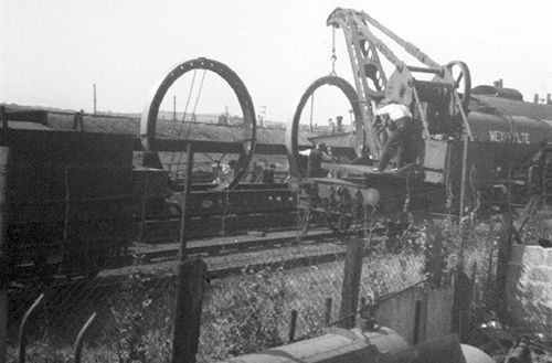
The 10' diameter Rings for a Mexican Cement Works
being loaded on a Railway Wagon by Hand Crane
on the railway line adjacent to the Tan Lane Foundry site.
Chapter 9 of Golden Hammer shows a picture of Gear Wheels destined for Canada.
Our final subject is of this Aluminium Pulley. It was cast at the foundry and machined by the Company. It was destined for HMTS Monarch.

Side view of the finished casting.
The proper name for it is a Cable Engine Sheave and the colour photograph, below, shows a series of them that make up the machinery that feeds the undersea Telephone Cable from the on board Cable storage tanks out and over either the bow or stern sheaves. HMTS Monarch was launched on the 8th August 1945 and was, at the time, the largest cable ship afloat. It was handed over to the GPO (as was then) in February 1946. She had the capacity to carry 1500 nautical miles of deep sea telegraph cable. In 1969 the GPO ceased to be a Government Department and the HMTS prefix was dropped; the ship was sold to Cable & Wireless Ltd and became CS Sentinel. In October 1977 she was sold for scrap.
I am indebted to Bill of the Atlantic Cable Website and for the permission to use the photograph of the Ship and the Cable Laying machinery.

Man beside the pulley gives some idea of size of the casting.

End view of the Pulley suspended from the
gantry outside the Machine Shop

The Cable laying engine installed in a sister ship to
the HMTS Monarch, showing the bank of Cable Sheaves
similar to the one cast by Garton & King.

HMTS Monarch
Updated January 2023
Top of Page
See also:
Flying the Flag — Great Exhibition 1851
Tan Lane Foundry — In the Foundry
Workforce — Taylor & Bodley
Sitemap / Contents
